



Technical parameters
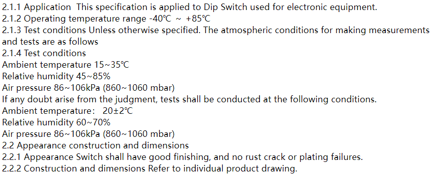
2.1 General
2.3 ENVIRONMENT RESISTANCE:
ITEM | DESCRIPTION | TEST CONDITIONS | REQUIREMENTS |
2.3.1 | Resistance Low Temperature | Before taking measurements, the sample should be allowed to sit in conditions of regular temperature and humidity for one hour according to the test set out below. To reiterate, it's important to keep the sample at normal levels before conducting any measurements. 1)Temperature : -40±3℃ 2)Time: 96 hours | 1)As shown in item 2.3.1-2.3.5 2)Contact Resistance: 2Ω max. |
2.3.2 | Resistance High Temperature | ,,。 Temperature : 85±2℃ Time: 96 hours | |
2.3.4 | Resistance Humidity | In order to conduct accurate measurements, it is important to follow the test set forth below. After obtaining the sample, it should be left in normal temperature and humidity conditions for at least an hour before any measurements are taken. This will ensure that the sample has acclimated to its environment and that the measurements are not affected by any changes in temperature or humidity. Taking the time to properly prepare the sample in this way will yield more reliable and accurate results in any testing process. 1) Temperature : 40℃±2℃ 2) Relative Humidity :90~95% 3) Time: 96 hours | 1)As shown in item 2.3.3-2.3.5 2)Contact Resistance: 2Ω max. 3)Insulation Resistance: |
2.5. SOLDERING CONDITIONS:
■ Condition for Soldering –EM(R) Series
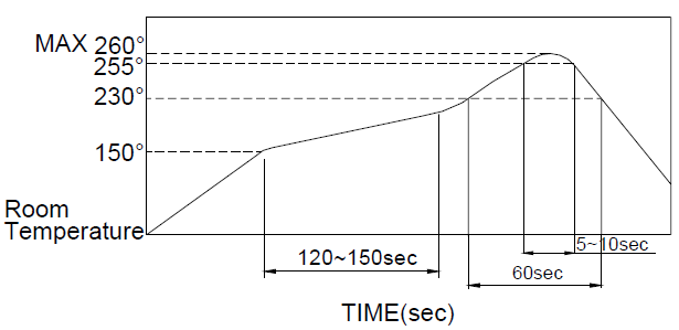
■ The condition mentioned above is the temperature on the Cu foil of the P.C.B surface. There are cases where board’s temperature greatly differs from switch’s surface temperature depending on board’s material, size, thickness, etc. Care, therefore, should be used not to allow switch’s surface temperature to exceed 260℃.
■ Manual Soldering
Soldering Temperature | Max.350℃ |
Continuous Soldering Time | Max. 5 seconds |
■ Precautions in Handling
1. Care should be exercised so that flux from the upper part of the printed circuit board does not adhere to the switch.
2. Don’t clean the switch body except with top tape sealed type, which can only spray of cleaning method from top of s/w.
3. Please make sure that there is no flux rose over the surface of the PCB
2.6 DURABILITY
2.6.1 | Operation Life | Measurements shall be made following the test set forth below: 1) 25mA, 24VDC resistive load 2) Rate of Operation: 15~20 cycles/ minute 3) Cycle of Operation: SWDHN(F)-V→1000 cycles. | 1)As show in item 2.3.2-2.3.3 2)Contact Resistance: 2Ωmax. (final-after test) |
2.6.2 | Stop Strength | A static load of 1kgf is applied in the operating direction and pulling direction operated for a period of 15 seconds. | There shall be no sign of damage mechanically.
|
2.6.3 | Vibration | Shall be vibrated in accordance with Method 201A of MIL-STD-202F 1) Frequency: 10-55-10 Hz 1 min/cycle. 2) Direction: 3 vertical directions including the direction of operation. 3) Test Time: 2 hours each direction.
| As shown in item 2.3.1-2.3.5 |
3. DRAWING & DIMENSION:

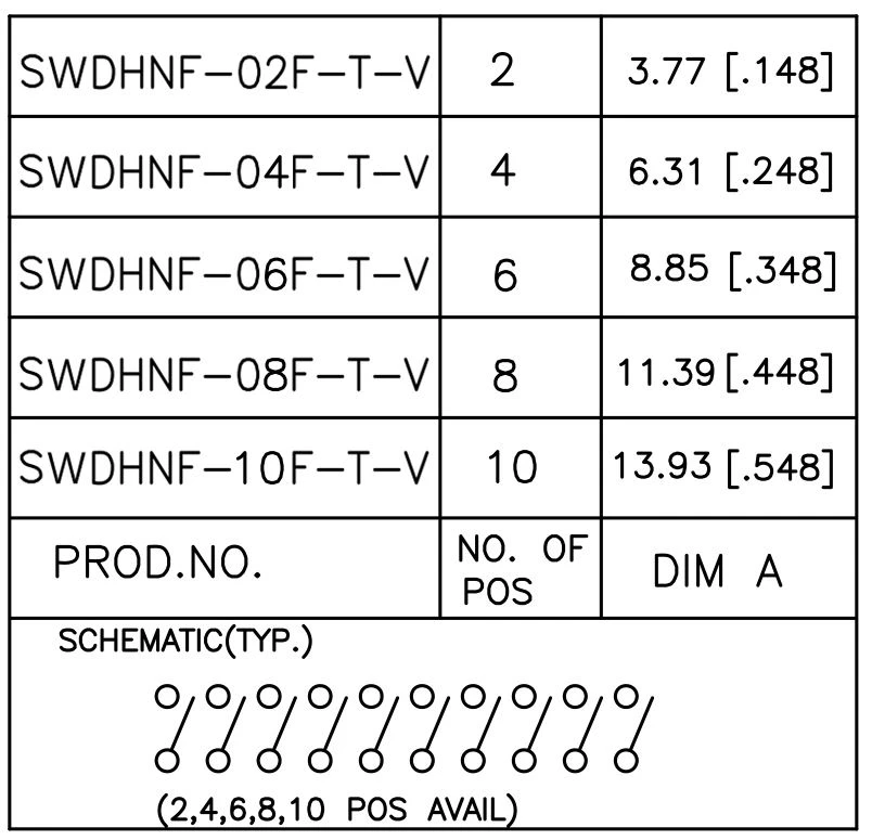
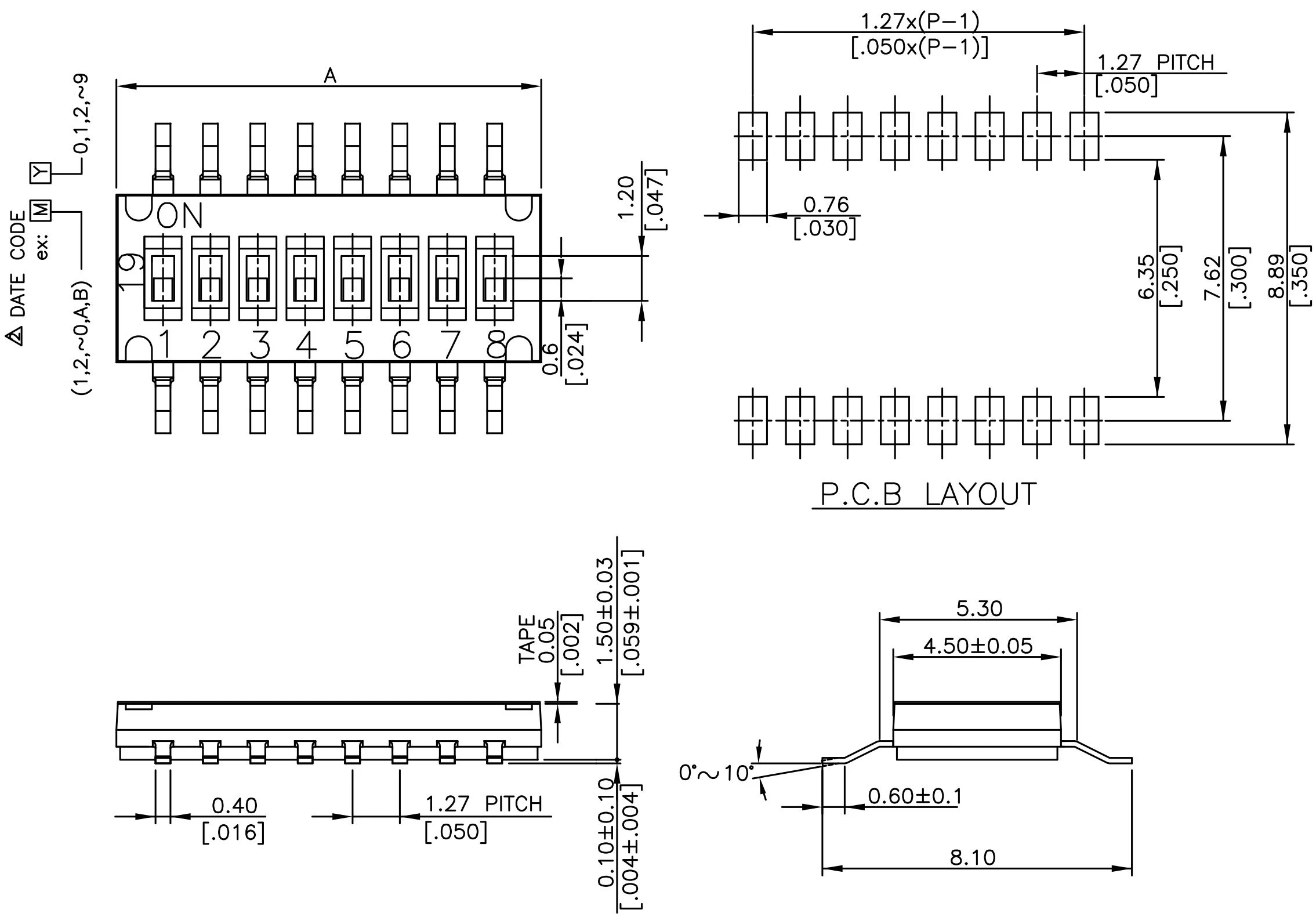
4.Remarks
PARTS LIST:
NO | NAME | QTY | MATERIAL | TREATMENT |
1 | Cover | 1 | High-temp. Thermoplastic Nylon UL94V-0 | Molded black |
2 | Actuator | * | High-temp. Thermoplastic LCP | Molded white |
3 | Contact | * | Phosphor bronze | Gold plated |
4 | Terminal | * | Brass | Gold plated |
5 | Base | 1 | High-temp. Thermoplastic Nylon UL94V-0 | Molded black |
6 | Tape | * | Katpon | - |
Returned plastic should not exceed 20%.
5.Delivery,shipping and service

6.FAQ

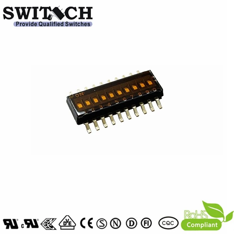
Hot Tags: dip switch 10 position, China dip switch 10 position manufacturers, suppliers, factory