


2.3. ELECTRICAL SPECIFICATION
NO. | Items | Test conditions | Requirements |
2.3.1 | Contact | After certain operations without any load, the small current (100 mA or less) should be evaluated by the voltage drop method at 1kHz. It is important to rearrange the original content and ensure that the generated content is highly similar in meaning. Applied position: Between terminal and terminal | 50mΩ MAX |
2.3.2 | Insulation | Test voltage: 100VDC, measured after 60 ±5s Applied position: 1)Between terminal and terminal 2)Between terminal and ground | 100MΩ MIN |
2.3.3 | Voltage proof | The designated test voltages have to be applied for a duration of 1 minute. Please create a substantially similar text by rephrasing the original content, while keeping in mind its main message. It is important that the generated text does not rely on any prior information obtained from ChapGPT. (Cut-off current:0.5mA) 1)Between terminal and terminal:500VAC (50~60Hz) | No dielectric breakdown shall occur |
2.3.4 | Capacitance | 1MHz±10kHz | 5 pF Max |
2.3.5 | Operation Force | Applied in the direction of operation ON→OFF OFF→ON |
200gf Max |
2.4. ENVIRONMENT RESISTANCE:
NO. | Items | Test conditions | Requirements |
2.4.1 | Low Temperature | After testing at -20±3℃ for 96 h, the switch shall be allowed to stand under normal room temperature and humidity condition for 1h, and then measurement shall be made within 1 h. water drops shall be removed. | (1)Contact resistance: 50mΩ MAX
(2)Insulation resistance: 100MΩ MIN
(3)Voltage proof: No dielectric breakdown shall occur.
(4)Operating characteristic: Operating characteristic variety Within ±10% of specified value .
No abnormalities shall be recognized in appearance and construction. |
2.4.2 | High Temperature | After testing at 70±2℃ for 96 h, the switch shall be allowed to stand under normal room temperature and humidity condition for 1h, and then measurement shall be made within 1 h. | |
2.4.3 | Steady Damp-heat | After testing at 40±2℃ and 90-95%RH for 96 h, the switch shall be allowed to stand under normal room temperature and humidity condition for 1h, and then measurement shall be made within 1 h. water drops shall be removed. | |
2.4.4 | Change of temperature | After 5 cycles of following conditions the switch shall be allowed to stand under normal room temperature and humidity condition for 1h, and then measurement shall be made within 1 h. water drops shall be removed. | |
2.4.5 | Salt mist | he switch shall be checked after following test: 1) Temperature: 35℃±2℃ 2) Salt solution : 5±1%(solids by mass) 1) Time: 24±1 hour After test,salt deposit shall be removed by running water.
|
2.5 WELDING PERFORMANCE
2.5.1 |
Solder ability | Switch test under such conditions and inspect after. 1)Variable temperature range :235±5℃; 2)Dip time:3±0.5s; |
The area of dip tin should capture the 95% impregnated area |
2.5.2 |
Resistance to soldering heat |
The switch will be inspect under such conditions below Temperature and impregnated time Manual Soldering Soldering Temperature Max.320℃ Continuous Soldering Time Max. 2 secondsWave reflow soldering Soldering Temperature Max.260℃ Continuous Soldering Time Max. 5 seconds |
All of the appearance, motor functions, electrical properties are no abnormal. |
2.6 DURABILITY
|
Life Test | An actuator shall be with a thrust of no great than 1 times switch power to 3,000 cycles. At a speed of 30 cycles for 1 minutes. |
1)Contact resistanc: 50mΩ MAX 2) Life time: 3) 3000 cycles |
2.6.2 | Stem Strength | And along the running direcition at apex handle (500g) on the strength test, time is 30 seconds. |
3.

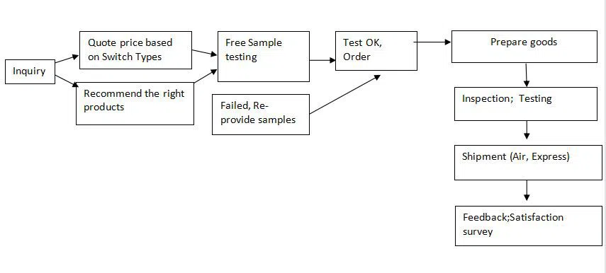
4.Order Process

Hot Tags: 6 pin dip switch, China 6 pin dip switch manufacturers, suppliers, factory